ANTHONY NISTOR // LINE FOLLOWER

Stackr Line Follower

A front add-on for Stackr. Five reflective sensors on a custom board read a black line, and the robot steers to stay on it.

// SYSTEM ARCHITECTURE

How the Add-On Reads the Line

A printed housing bolts to the front of Stackr and holds a custom sensor board just above the floor. Five QRE1113GR reflective sensors look down through windows in the housing. A ribbon cable carries those readings to the controller on the robot, which steers the wheels to keep the black line under the bar.

  • Five Reflective Sensors QRE1113GR sensors sit in a row on the board. Each one reports whether the floor under it is the black line or the white surface.
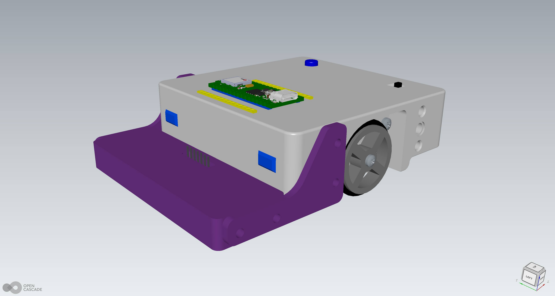
  • Printed Front Mount Purple brackets and a slotted cover bolt to the nose of Stackr and hold the board at a fixed height.
  • Ribbon Cable A seven-wire cable runs from the board header up to the controller on top of the robot.
LINE_TRACK.LOG ACTIVE
1. SENSE

Five sensors look at the floor under the bar

LINE
↓ Send the readings
2. READ

The ribbon cable carries the signals to Stackr

CABLE
↓ Stay on the oval
3. STEER

The robot turns to keep the line under the bar

TRACK
// LINE RUN

Following the Oval

Stackr with the sensor bar on a black oval drawn on a white surface.

LINE_RUN.MP4 LIVE DEMO

On the Line

The add-on rides at the front while Stackr follows the black oval.

// HARDWARE & SOFTWARE

System Component Breakdown

01

Sensor Board

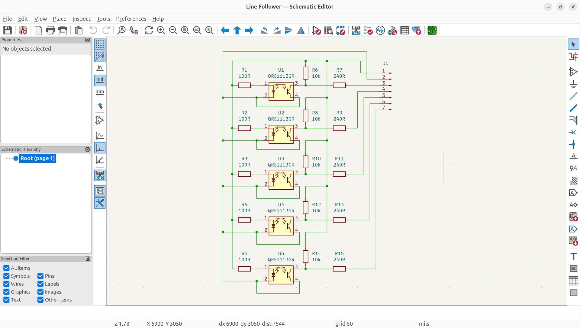
A custom PCB marked RobotiX One, with five sensor channels and a seven-pin header.

02

QRE1113GR

Five reflective optical sensors, one for each window in the printed housing.

03

Printed Housing

Purple side brackets, a tray with five square windows, and a cover with a cable slot.

04

Stackr

The host robot. The bar bolts to the front and the cable plugs into the controller on top.

// PROJECT MEDIA

Build Photos

The bar on Stackr, the sensor board, the printed parts, and the CAD and KiCAD drawings.
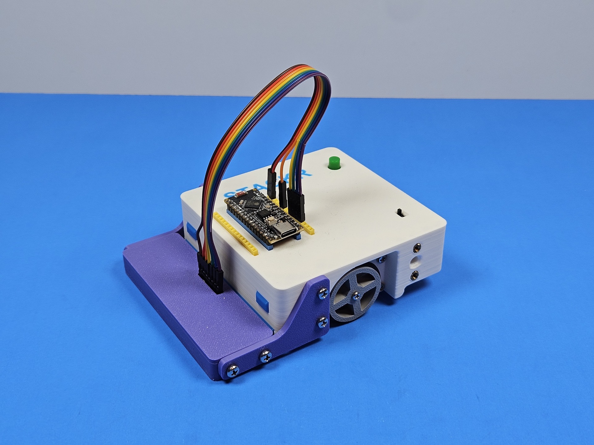
On Stackr
CLICK TO ENLARGE

On Stackr

The purple sensor bar bolted to the front, with the ribbon cable up to the controller.
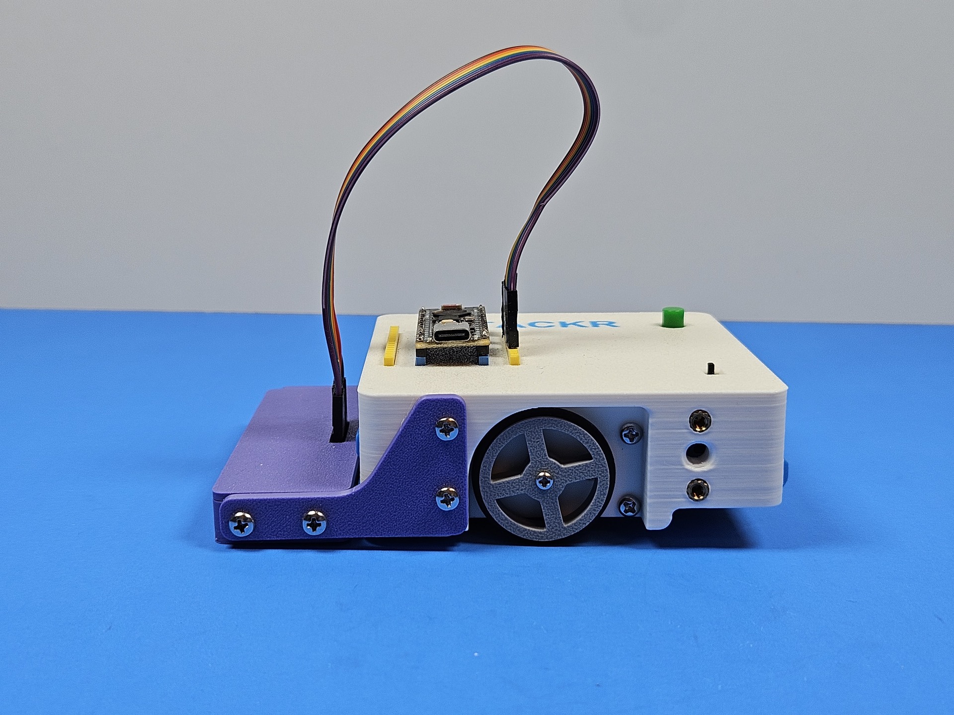
Side View
CLICK TO ENLARGE

Side View

The bar sits ahead of the wheel so the sensors lead the robot.
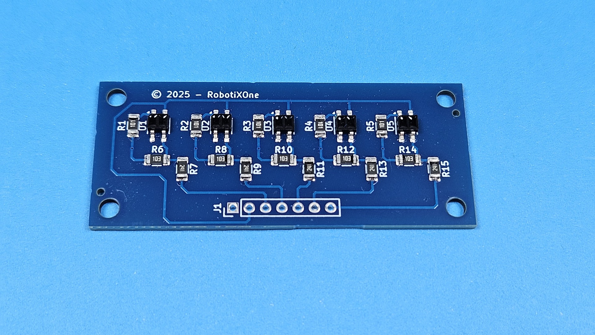
Sensor Board
CLICK TO ENLARGE

Sensor Board

The finished board with five reflective sensors and the header along the near edge.
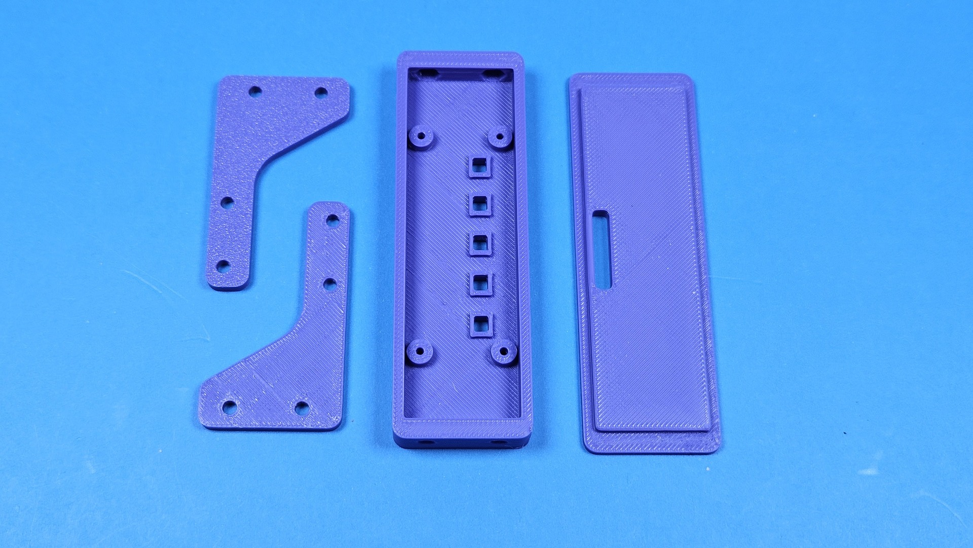
Printed Parts
CLICK TO ENLARGE

Printed Parts

Two brackets, the sensor tray, and the cover before assembly.
Schematic
CLICK TO ENLARGE

Schematic

The KiCAD schematic: five QRE1113GR channels and a seven-pin connector.
CAD Assembly
CLICK TO ENLARGE

CAD Assembly

The FreeCAD model of Stackr with the purple bar on the front.

// SLIDESHOW

All Project Pictures

26 photographs and drawings from this build.

20260413_110255.jpg 1 / 26
20260413_110255.jpg
// TECHNICAL SPECIFICATIONS

System Parameters & Metrics

PARAMETER SPECIFICATION / VALUE
Host Stackr
Sensors Five QRE1113GR reflective sensors
Board Custom PCB marked RobotiX One
Connector Seven-pin header and ribbon cable
Mount Printed purple brackets and sensor housing
Track Black oval line on a white surface
Design FreeCAD assembly and KiCAD schematic